# Power Control
Digital power control was implemented by rewiring the power switch connections to a relay. The switch can be used indirectly to power the machine by wiring to a digital microcontroller pin. The main power switch is a double pole, single throw (DPST) switch, connecting both the live and neutral circuits. To replace this a dual relay was used. The relay used requires 12V to switch so a mosfet is needed to switch from the microcontroller output (5V with Arduino) to a higher 12V circuit. It would have been better to use a relay with a 5V coil voltage but this is what I had available.
# Components
- T92P7D22-12 DPST-NO Relay [datasheet]
- 277V, 30A
- Dual relay
- 12V coil voltage
- 12VDC power supply
- IRF520 Mosfet [datasheet]
- Gate threshold voltage 4V
- Drain-source voltage 100V
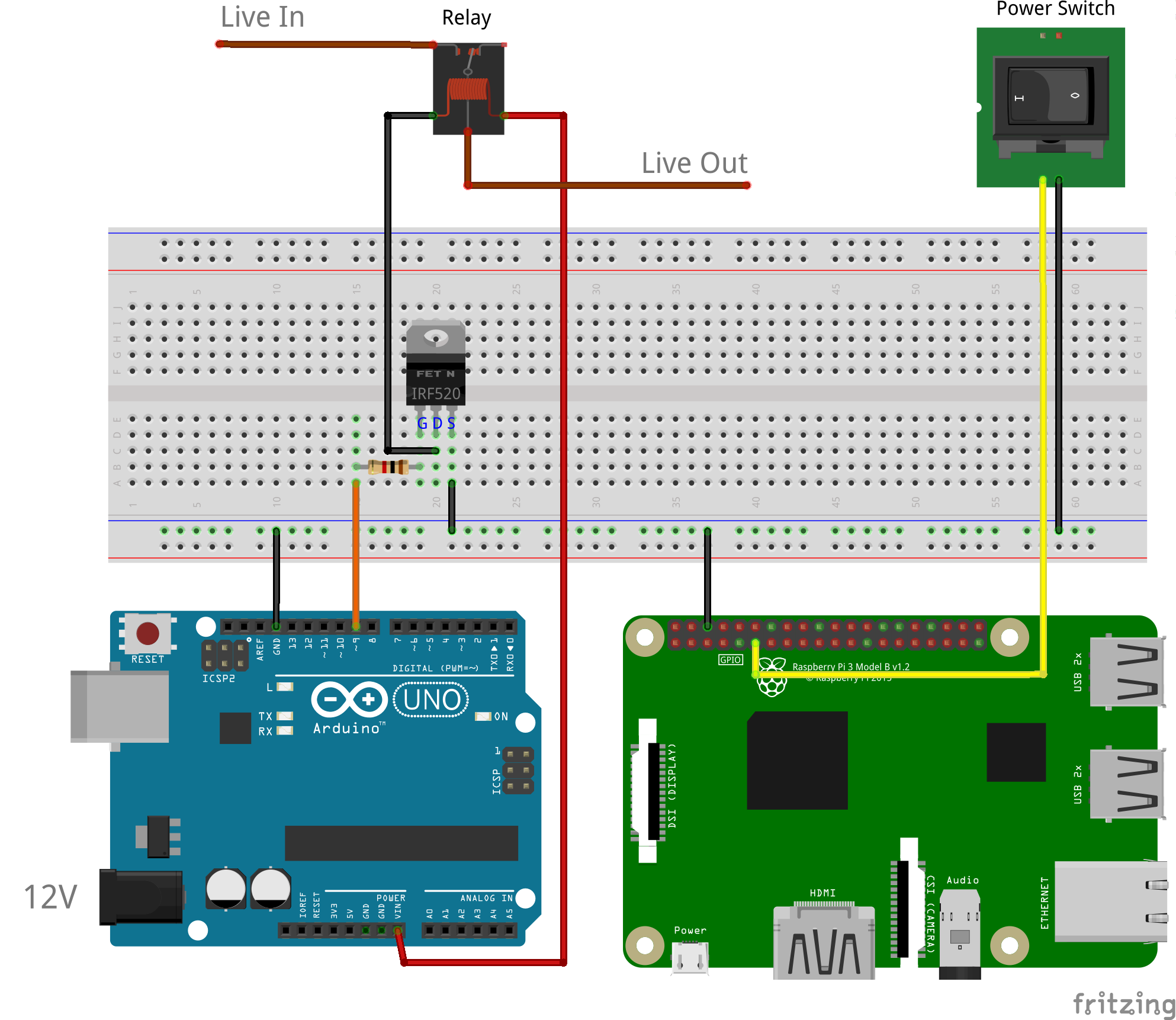
# Installation
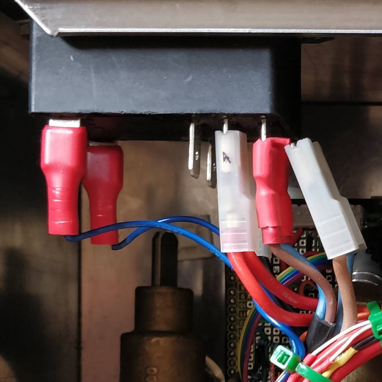
# Wiring
The Arduino switches the mechanical relay with 12V (supplied through barrel jack) with an IRF520 mosfet. A 1kΩ pull-down resistor is used to ensure the mosfet input is at 0V when the output in not high. The raspberry pi detects the switch operation via a GPIO pin. This does not require a pull up/down resistor as they are built in.
# Software
# Raspberry pi interrupt
The raspberry pi gpiozero Button class is used to detect switch operation which then communicates to the Arduino over I2C via Celery asyncrhonus tasks.
from gpiozero import Button

button_power = Button(17)
button_power.when_pressed = trigger_machine_on
button_power.when_released = trigger_machine_off
The python interrupt file is registered as a django management command:
$ python manage.py raspi_interrupt
# Arduino relay control
A generic relay control class was used to operate the relays through the standard Arduino interface with the relevant on() method being:
void RelayOutput::on() {
  status_ = true;
  digitalWrite(pin_, HIGH);
};